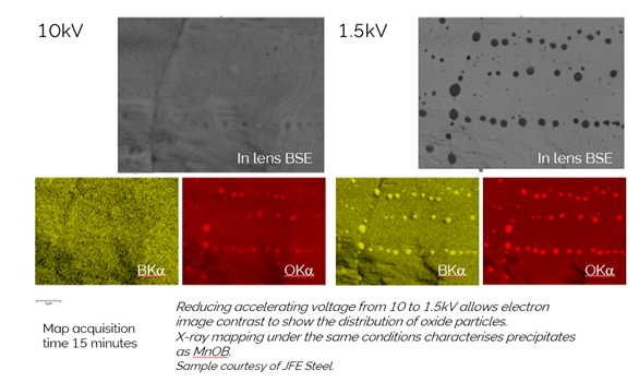
Have you ever been in the situation where you can image something in the SEM, but you can’t determine the associated element make-up because when you change conditions for EDS analysis you can no longer even see the structures of interest? Then this blog may be for you. The ‘imaging sweet-spot’ for high spatial resolution, and/or surface sensitive analysis of nano-structures and coatings uses low kV and short working distance. These are conditions under which conventional EDS detectors provide little useful information, designed as they are for higher kV, longer working distance conditions. There is an alternative,
however, a special type of EDS detector - Ultim Extreme - designed to operate and add useful elemental information to analysis being carried out in the imaging sweet-spot. How did this come about, and what new types of characterisation are possible with this detector? Read this interview with Dr Kaoru Sato, and Mr Takaya Nakamura, of JFE Techno in Japan to find out more.
Simon’s story
My story starts on a warm spring April day on the southern outskirts of Paris back in 2015. There I was meeting Dr Sato, then working for JFE Steel in Japan. We were there to combine two big ideas, from Dr Sato the ‘Imaging Sweet Spot’ the idea of combining as many sensors as possible to image samples in the SEM at short working distance and low kV, to see unique information about the surface and structure of materials. From Oxford Instruments a revolutionary new windowless detector with unique geometry designed to collect EDS information where conventional detectors could not operate. These ideas had been converging since a meeting I had with Dr Sato in Chiba, Japan, a number of years earlier, where he challenged Oxford Instruments to think about high spatial nano-analysis from a ‘Sweet-spot perspective’. The test yielded some very interesting results, particularly some maps of boron and oxygen from some nano-inclusions in a steel sample.
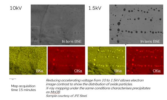
These maps highlighted the potential of sweet-spot analysis so clearly. At 1.5 kV, inclusions in this sample are clearly visible but going to 10 kV, for traditional EDS, makes them disappear; they are just too thin. At 10 kV, the EDS also gives little information, which supports the statement I always make regarding imaging and EDS: ‘if you can’t see it in the electron image, don’t expect to characterise it with EDS’. The crucial thing with our new approach to analysis, was, for the first time, we could collect EDS at 1.5 kV, short working distance, i.e. in the ‘the sweet-spot’, and see clearly with EDS the elements contained in these inclusions.

More frustrating was our first attempt to map the distribution of 10 nm sized Nb carbide inclusions in a second steel sample. We managed to collect some spectra showing the NbMz line at 1 or 2 kV from these inclusions, but the sample preparation facilities were not available to create a clean surface needed to be able to image the sample surface clearly.
Coming back to today, the interview with Dr Sato and Mr Nakamura brought this new beginning to mind, as we see how JFE Techno are practically achieving unique results at ‘the imaging sweet-spot’ with Ultim Extreme. Also, an example given in the interview of successful X-ray mapping of a Nb-coating in a battery material, brings our first efforts to detect the ultra-low energy NbMz line back in 2015 to mind.
Some context on surface coatings and doping in battery materials from Alexandra
Battery (cathode precursor) powder particle coatings are a highly relevant topic these days. Particle surface coating and particle composition doping are two distinct methods used to improve cycling stability of high-voltage LiCoO2.
- The combination of the two has also been attempted (Kim and Park, 2021). In this case, K doping was used to increase the capacity of Li-rich oxide along with Nb oxide coating. The synergy between the two methods is based on preventing the formation of the interfacial layer (between cathode and electrolyte) by side reactions that leads to unstable cyclability and (rapid) capacity fade.
- There are different combinations of elements used for coating or doping – many of them tried at an experimental stage, e.g. trace Ti-Mg-Al co-doping has also been found to promote stability of LiCoO2 cyclability above 4.5 V by inhibiting the phase transitions taking place above that voltage (Zhang et al., 2019).
- Doping has been reported to work with common – for battery manufacturing – elements, too: Ni and Mn co-doping was found to stabilise the structure of LiCoO2 and consequently cycling through inhibiting undesirable phase transitions – again in a synergistic manner; the doped lattice of LiCoO2 comes with larger unit cell parameters which enable Li ion transfer leading to enhanced capacity retention (Wang et al., 2020).
The bottom line is that all those methods are used to modify the electrochemical behaviour and structural transformation of cathode materials. Thus, making them last longer by preserving them for longer in their initial state (compositionally & structurally). Having talked about cathodes, we should also mention that anodes are not excluded from doping either. Boron has been found to be of benefit for not only lithium-sulphur battery cathodes (sulphur/carbon) (Yang et al, 2014) but also for B-doped graphene anodes of Na-ion batteries (Ling and Mizuno, 2014). In other words, the investigation for improved formulations is ongoing and promising; making the point that there is still margin for technological advances of known materials apart from developing & testing new materials.
Simon concludes:
So dopants and coatings in battery cathode material (and occasionally anode) are an important area of materials development for improving battery performance. The capability to not only image the ultra-thin coatings on battery materials but also to characterise their chemistry is powerfully demonstrated by Dr Sato and Mr Nakamura, with their imaging of Nb on the cathode particle.
By combining an idea like the imaging ‘sweet spot' with technology like Ultim Extreme, we can help meet the most difficult characterisation challenges necessary to develop new materials and better batteries. It’s great to see these concepts and technologies being put to such practical use.
References
- Kim HG, Park YJ. Synergy effect of K doping and Nb oxide coating on Li 1.2 Ni 0.13 Co 0.13 Mn 0.54 O 2 cathodes. Journal of Electrochemical Science and Technology. 2021 Apr 15;12(4):377-86.
- Wang Y, Cheng T, Yu ZE, Lyu Y, Guo B. Study on the effect of Ni and Mn doping on the structural evolution of LiCoO2 under 4.6 áV high-voltage cycling. Journal of Alloys and Compounds. 2020 Nov 25;842:155827.
- Zhang, JN., Li, Q., Ouyang, C. et al. Trace doping of multiple elements enables stable battery cycling of LiCoO2 at 4.6 V. Nat Energy 4, 594–603 (2019). https://doi.org/10.1038/s41560...
- Ling C, Mizuno F. Boron-doped graphene as a promising anode for Na-ion batteries. Physical Chemistry Chemical Physics. 2014;16(22):10419-24.
- Yang CP, Yin YX, Ye H, Jiang KC, Zhang J, Guo YG. Insight into the effect of boron doping on sulfur/carbon cathode in lithium–sulfur batteries. ACS applied materials & interfaces. 2014 Jun 11;6(11):8789-95.


